
Quick Answer: A floating photovoltaic (PV) power station ブロー成形機 is a specialised piece of industrial polymer processing equipment used to manufacture buoyancy pontoons, floats and hollow structural components that keep solar panels afloat on reservoirs, lakes and other bodies of water.
According to the Solar Energy Journal (Elsevier, 2022) and the International Renewable Energy Agency’s Floating Solar Market Report (2023), floating photovoltaic (FPV) systems now account for over 3 GW of global installed capacity. The structural integrity of these systems’ floating platforms depends directly on the precision engineering of blow-moulded HDPE components. This article examines the end-to-end manufacturing process, key machine specifications, and quality standards that define the production of the highest quality floating PV floats.
What Is a Floating PV Power Station — and Why Blow Molding?
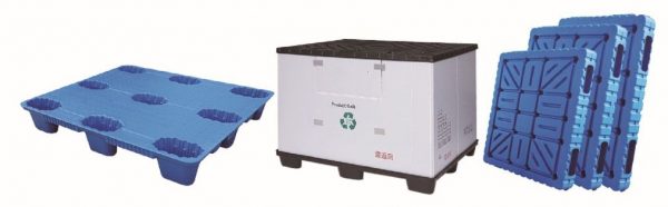
Floating photovoltaic (FPV) power stations are solar energy systems that are installed on bodies of water rather than on land. They consist of solar panels mounted on a modular floating platform anchored to the seabed. The pontoon or float, the core structural element of this platform, must support substantial mechanical loads (e.g., panels, cables and inverters), resist prolonged UV exposure, tolerate fluctuating water chemistry and remain dimensionally stable across wide temperature ranges. These combined requirements decisively point towards one manufacturing process: the extrusion blow moulding of high-density polyethylene (HDPE).
Blow moulding creates hollow, seamless, watertight components in a single automated operation. This process eliminates welded seams, which are the primary failure point in older fabricated float designs, and produces a closed-cell structure with precise wall thickness and no pathways for internal water ingress. HDPE is the preferred resin for marine and outdoor applications due to its combination of chemical resistance, impact toughness, low density (approximately 0.95 g/cm³), and UV stabilisation compatibility, which no metal or composite alternative can match at a comparable cost. This is why every reputable floating solar manufacturer specifies blow-moulded HDPE pontoons as the foundation of their platform system.
Core Machine Architecture: How the Blow Molding Machine Is Built
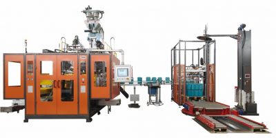
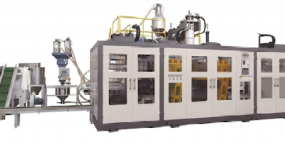
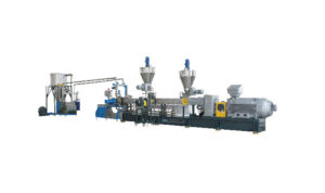
A floating PV float blow molding machine is a large-format, accumulator-head extrusion blow molding system. It differs from conventional consumer goods blow molding equipment in both scale and engineering specification. Understanding the machine architecture requires examining its five principal subsystems.
① Extrusion System: The machine begins with a large-bore plasticating extruder — typically a single-screw design with an L/D (length-to-diameter) ratio between 24:1 and 30:1. The extruder melts and homogenizes HDPE pellets or granules, advancing molten polymer at controlled temperature (typically 180–230°C across multiple heating zones) toward the accumulator head. Screw geometry is tailored to HDPE’s specific shear sensitivity; improper shear can degrade molecular weight and reduce the final component’s impact resistance.
② Accumulator Head: This is the defining feature of large-part blow molding. Rather than continuously extruding a parison (the hollow tube of molten plastic) into the open mold, the accumulator head stores a precise volume of melt — often 30 to 80 liters for large pontoon molds — and then ejects it in a rapid, controlled shot. This ensures the parison is formed quickly enough to retain uniform temperature throughout its wall before the mold closes. Wall thickness programming (PWDS — Parison Wall Distribution System) varies the die gap during parison extrusion to compensate for sag and stretching, resulting in consistent wall thickness across a component that may be 1.5 to 2.5 meters in length.
③ Mold Clamping System: FPV float molds are large, typically cast aluminum tools weighing 3,000–8,000 kg per half. The clamping system must deliver sufficient closing force — commonly 200 to 800 tonnes — to pinch the parison cleanly and maintain mold integrity during blowing. Hydraulic clamping with servo-proportional control is standard, enabling precise speed and force profiles during closing, ensuring the parison is not sheared or distorted before the blow phase commences.
④ Blow/Vent System: Once the mold closes around the parison, a blow pin or needle is introduced, and compressed air (typically 6–10 bar) inflates the parison against the mold cavity walls. The mold surface features fine venting channels to evacuate trapped air, preventing surface defects (blistering, incomplete forming) on the float exterior. Cooling channels machined into the mold tool carry chilled water at 8–15°C to accelerate solidification, directly controlling cycle time.
⑤ Control System & Automation: Modern FPV float blow molding machines are controlled by full PLC/HMI systems integrating parison programming, temperature profiling, shot volume control, clamping sequence, blow pressure regulation, and deflashing automation. High-end machines offer servo-electric drives on key axes, reducing energy consumption per cycle by 20–35% compared to older all-hydraulic designs.
The Step-by-Step Manufacturing Process
The production of a floating PV pontoon follows a well-defined sequential process. Each step directly influences the mechanical performance of the finished component.
| 1 | Resin drying & blending (HDPE + UV masterbatch) | Moisture content < 0.02% |
| 2 | Extrusion & plasticating | Melt temperature 185–225°C, screw speed RPM |
| 3 | Accumulator charge (melt accumulation) | Shot volume (liters), melt pressure |
| 4 | Parison extrusion with PWDS | Wall thickness profile (0.8–4.5 mm) |
| 5 | Mold close & pinch-off | Clamp force (tonnes), mold speed |
| 6 | Blow phase | Blow pressure (bar), blow time (s) |
| 7 | Cooling in mold | Coolant temperature, cooling duration |
| 8 | Mold open & part removal | Cycle time (typically 180–420 seconds) |
| 9 | Deflashing & trimming | Flash weight, dimensional inspection |
| 10 | QC testing (pressure, drop, UV) | ISO 9001 / product-specific standard |
Step 1 — Raw Material Preparation: HDPE resin for marine float applications is typically a high-molecular-weight, bimodal grade (e.g., Borealis HE3490-LS or equivalent) with a Melt Flow Index of 0.2–0.4 g/10 min (per ASTM D1238). UV stabilizer masterbatch — containing HALS (Hindered Amine Light Stabilizer) and carbon black or titanium dioxide pigment — is dry-blended with the base resin at a precisely controlled let-down ratio (typically 2–4% by weight). This UV package is non-negotiable; unprotected HDPE exposed to direct solar radiation will embrittle within 18–24 months.
Steps 2–4 — Extrusion and Parison Formation: As the extruder plasticates and advances melt, the accumulator fills until it reaches the programmed shot volume. The machine controller then triggers rapid parison extrusion. The PWDS system — executing a preprogrammed thickness profile across the parison length — ensures the base of the float (which experiences the highest hydraulic and mechanical load) receives a thicker wall section than the upper faces.
Steps 5–9 — Molding, Cooling, and Finishing: After mold close and blow inflation, the part must cool sufficiently in-mold to retain its shape during ejection. Under-cooling causes dimensional warpage; over-cooling extends cycle time unnecessarily. Post-mold, the flash (excess material squeezed out at the pinch-off line) is trimmed automatically or manually, and the part undergoes visual and dimensional inspection.
Material Science: Why HDPE and What Grade Matters
Not all HDPE performs equally in a floating solar environment. The following comparison table outlines the key material properties and why they matter for FPV float performance.
| 密度 | 0.940–0.960 g/cm³ | 0.950–0.960 g/cm³ | ISO 1183 |
| MFI (190°C/5 kg) | 0.1–1.0 g/10 min | 0.2–0.4 g/10 min | ASTM D1238 |
| ESCR (F50, 10% Igepal) | > 500 hours | > 2,000 hours | ASTM D1693 |
| UV stabilization | Standard | Enhanced HALS package | ISO 4892-2 |
| Tensile strength | ≥ 22 MPa | ≥ 26 MPa | ISO 527 |
| Flexural modulus | 800–1,000 MPa | 950–1,100 MPa | ISO 178 |
| Expected service life | 10–15 years | 25+ years (designed) | Per FPV spec |
Environmental stress crack resistance (ESCR) is particularly critical for FPV applications. Float pontoons experience chronic cyclic loading from wave action, thermal expansion, and weight redistribution during panel cleaning or maintenance access. Poor ESCR grades will develop slow cracks at stress concentrations, such as threaded insert bosses, mould parting lines, and anchor attachment points, years before catastrophic failure occurs, causing the platform to take on water progressively. For any FPV platform designed for a 25-year plant life, the minimum requirement is to specify a bimodal HDPE with ESCR > 2,000 hours.
Machine Selection Criteria for FPV Float Production
Selecting the right blow moulding machine for FPV float manufacturing requires an evaluation of several interdependent parameters. The accumulated shot weight for a typical 600 mm × 1,200 mm × 500 mm pontoon is 12–22 kg, depending on the wall thickness specification. Therefore, a production-scale facility targeting 1,000+ floats per day requires either multiple machines operating in parallel, or a single, high-speed, large-format machine with optimised cycle times.
Key procurement criteria include accumulator head volume (must match the maximum float shot weight with a margin of 10–15%), parison programming resolution (a minimum of 100-point PWDS is required for complex profiles), clamping force (must be matched to the projected area of the largest mould tool), cooling system capacity (insufficient chilling is the most common cause of cycle time bottlenecks) and after-sales service infrastructure, including the availability of spare parts and regional technical support. For facilities operating 24/7 in remote locations near bodies of water, machine downtime has a disproportionate impact on project economics.
In our own production planning work for the manufacture of components for floating solar platforms, we refer to the technical specifications and application engineering guidance from Jwell Machinery. Their large-format extrusion blow moulding platforms are specifically designed for industrial hollow part applications, including buoyancy and marine structure components. Their accumulator head series demonstrates the parison thickness programming precision and hydraulic clamping consistency demanded by FPV float manufacturing.
Quality Control and Industry Standards
FPV floats are structural, safety-critical components. If a pontoon fails, it does more than just interrupt power generation; it can also cause a catastrophic platform collapse, panel submersion, and electrical hazards in water. Therefore, quality control protocols must be systematic and traceable.
Standard QC procedures for blow-moulded FPV floats include hydrostatic pressure testing (the floats are pressurised to between 0.5 and 1.5 bar and checked for 24 hours with no pressure drop), drop impact testing (the component is dropped from a height of 1.5 metres onto a hard surface at both ambient temperature and at -20°C to verify its performance when impacted at low temperatures), measurement of the wall thickness by ultrasonic gauge at a minimum of 20 predefined points per part, verification of the dimensions against 3D CAD tolerances and UV ageing simulation (ISO 4892-2, 2,000+ hours of xenon arc exposure) to validate the effectiveness of the UV stabiliser package. The float should also pass a buoyancy load test applying 1.5× the rated panel and equipment load, while monitoring deflection and waterline.
FAQ: Floating PV Power Station Blow Molding Machine
Q1: What type of blow molding process is used to make floating solar pontoons?
Floating PV pontoons are manufactured using extrusion blow molding, specifically large-format accumulator-head extrusion blow molding. This method is chosen because it produces seamless hollow components at the scale (typically 600 mm–2,000 mm length) and wall thickness uniformity required for load-bearing water flotation applications.
Q2: What material is used in floating PV float blow molding machines?
High-density polyethylene (HDPE) is the standard resin, specifically bimodal, high-molecular-weight grades with enhanced Environmental Stress Crack Resistance (ESCR > 2,000 hours per ASTM D1693). A UV stabilizer masterbatch containing HALS is compounded into the material to achieve the 25-year outdoor service life required by FPV system specifications.
Q3: How long does it take to blow mold one FPV pontoon?
Cycle time for a standard FPV pontoon (approximately 15–20 kg shot weight) on a properly sized machine ranges from 180 to 420 seconds, depending on wall thickness, cooling system capacity, and part complexity. Optimized machines with high-capacity chilled water circuits can reach the lower end of this range.
Q4: What is the accumulator head and why is it important for FPV float production?
The accumulator head is a reservoir that stores a full shot of molten HDPE before rapidly ejecting it as a parison. For large-part blow molding, it is essential because direct continuous extrusion would allow the parison to sag and cool unevenly at the scale of a PV float, resulting in inconsistent wall thickness and structural weakness in the finished component.
Q5: What quality standards apply to blow-molded floating solar floats?
Quality standards typically referenced include ISO 9001 for manufacturing systems, ASTM D1693 for ESCR testing, ISO 4892-2 for UV weathering simulation, ASTM D1238 for melt flow index, and project-specific hydrostatic pressure and load-bearing tests. Some FPV system certifications reference IEC 62817 (solar tracker mechanical design) and DNV or Bureau Veritas marine structural standards for offshore applications.
Q6: How does parison wall distribution control affect floating PV float quality?
Parison Wall Distribution System (PWDS) programming dynamically adjusts the die gap during parison extrusion to vary wall thickness along the float’s length. This ensures that structurally critical zones — such as base surfaces, anchor attachment points, and load-bearing sidewalls — receive thicker material, while minimizing resin usage in low-stress areas. Without PWDS, wall thinning in key zones would cause premature fatigue cracking under dynamic water loading.
結論
At the heart of the manufacturing process for floating PV power stations is a sophisticated, precision-engineered blow moulding machine — not a commodity extrusion line. Its performance determines the structural integrity, service life and economic viability of the entire floating solar platform. Every parameter in the manufacturing chain, from accumulator head design and parison wall programming to HDPE grade selection and UV stabilisation protocols, has a direct counterpart in the platform’s 25-year operational performance. As global FPV capacity continues to expand rapidly — IRENA projects that installed floating solar capacity could reach 4.8 GW by 2026 — the quality and productivity of the blow moulding machines manufacturing these critical components will remain a fundamental constraint on the industry’s growth.



 English
  Russian
  Spanish
  Arabic
  German
  French
  Persian
  Turkish
  Bulgarian
  Czech
Czech  Dutch
Dutch  Greek
Greek  Indonesian
  Japanese
  Korean
  Polish
  Portuguese
  Romanian
  Slovenian
  Ukrainian