
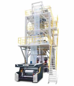
Quick Answer: A heavy-duty FFS (Form-Fill-Seal) [MÁQUINA DE FILM Soplado] is a specialised co-extrusion system designed to produce multi-layer polyethylene film with precise control over thickness, mechanical strength, and sealing properties. This film is used for industrial packaging applications such as cement bags, fertiliser sacks, and chemical liners.
According to the Plastics Technology Manufacturing Handbook (Hanser Verlag, 2021) and the technical guidelines published by European Plastics Converters (EuPC), the FFS blown film process involves resin plastication, bubble formation, multi-layer die distribution, and inline quality control, all of which are integrated into a continuous production loop. This loop is capable of achieving sustained output rates of over 400 kg/h on modern, high-performance lines. The Journal of Applied Polymer Science (Vol. 138, 2021) further confirms that optimising the blow-up ratio (BUR) and die gap geometry in FFS configurations is essential for achieving the tensile strength and dart impact resistance required by UN-certified heavy-duty packaging standards.
What Is an FFS Heavy-Duty Blown Film Machine — and Why Does the Distinction Matter?
In the plastics processing industry, the term ‘FFS blown film machine’ is often used loosely, but it correctly refers to a bespoke extrusion platform whose seamless tubular film output is specifically designed to run on automatic Form-Fill-Seal packaging equipment. It is not a generic blown film line that has been repurposed for heavy-duty applications. Rather, it is a distinct machine architecture in which every process parameter — from screw geometry and cooling ring design to winding tension — is calibrated to meet the unique mechanical and dimensional requirements of heavy-duty packaging film.
FFS heavy-duty applications encompass a demanding range of end uses:
① open-mouth and valve bags for cement (typically 25–50 kg net weight),
② bulk liners for chemical powders and granules,
③ industrial sacks for fertilizers, animal feed, and construction minerals,
④ stretch-hood films for pallet unitization.
What unites all of these applications is the requirement for a film that simultaneously offers high puncture resistance, consistent layer adhesion, reliable hot-tack and cold-seal performance, and the dimensional stability necessary to run at speeds of 40–120 bags per minute on downstream FFS equipment without tear propagation or seal failure.
The distinction from standard blown film production is therefore not merely one of scale — it is fundamentally one of performance specification. A standard blown film line optimized for agricultural mulch film or consumer packaging film is designed around different resin chemistries, die geometries, and winding systems than an FFS line designed for industrial sack production. Understanding this difference is the entry point to understanding how FFS heavy-duty blown film machines actually work.
Resin Selection and Co-Extrusion Layer Architecture
The functional performance of FFS heavy-duty film is determined not at the extruder stage, but at the material selection stage. Modern FFS heavy-duty blown film lines are almost exclusively co-extrusion systems, typically with three or five layers, because no single polyethylene grade can satisfy the simultaneous requirements for stiffness, toughness, sealability, and printability demanded by industrial heavy-duty packaging.
The most common resin architecture for a three-layer FFS structure allocates specific functions to each layer:
Outer Layer (A): Usually a linear low-density polyethylene (LLDPE) or medium-density polyethylene (MDPE) with a high melting point. This layer is designed to be receptive to corona treatment, to adhere to printing inks, and to resist external abrasion. C6 or C8 metallocene LLDPE grades are increasingly favoured here due to their narrower molecular weight distribution and superior surface quality.
Core Layer (B): The structural backbone of the film, typically made from high-density polyethylene (HDPE) or a blend of HDPE and LLDPE. The HDPE component provides stiffness, tensile strength, and barrier properties, while the LLDPE component reduces brittleness and improves impact resistance. This layer usually accounts for 60–70% of the total film thickness in heavy-duty applications.
Inner Layer (A or C): The sealing layer is formulated with low-melting LLDPE or very low-density polyethylene (VLDPE) to ensure reliable heat seal initiation at the temperatures and dwell times used by FFS machinery. Metallocene-catalysed grades are particularly valued here for their tight melting range, which provides a consistent and narrow sealing window that FFS machines can exploit at high speed.
The total film thickness for heavy-duty FFS applications typically ranges from 100 to 250 microns, depending on the fill weight and the mechanical stress profile of the end use. Cement bags, which are subjected to dynamic impact loading during stacking and transportation, are commonly specified at 150–200 microns with dart impact values exceeding 800 g (ASTM D1709 Method A) and machine-direction tensile strength exceeding 45 MPa.
The Blown Film Extrusion Process: From Pellet to Bubble
The core processing sequence of an FFS heavy-duty blown film machine follows the principles of the tubular blown film process, but with engineering refinements at each stage to achieve the consistency and output stability that industrial heavy-duty film production demands.
① Plastication and Melt Delivery
Each co-extrusion layer is fed from a dedicated extruder — usually a heavy-duty 45:1 L/D barrier screw extruder — where solid polymer pellets or granules undergo progressive melting through conduction, convection, and viscous shear heating. The barrier screw design physically separates the solid bed from the melt pool, thereby eliminating any unmelted particles that could otherwise create variations in thickness or stress concentration points in the finished film. In a 3-layer line, three extruders simultaneously feed melt streams into the co-extrusion die. A 5-layer line has an additional two extruder circuits.
The melt temperature at the die inlet is usually kept between 190°C and 230°C, depending on the resin grade. Melt pressure within the die manifold is continuously monitored. Even minor variations in melt temperature of ±5°C across the die circumference will produce measurable variations in the thickness of the blown bubble, which is why modern FFS lines use high-precision temperature controllers with response times of less than one second.
② Co-Extrusion Die and Bubble Formation
The co-extrusion die is the most mechanically complex component of the blown film line in FFS. In a spiral mandrel co-extrusion die, each melt stream enters through a separate inlet port and is distributed around the die’s circumference via spiral channels cut into the mandrel’s concentric assemblies. This geometry ensures that each melt layer is uniformly distributed around the circumference before all layers converge at the die exit to form a single co-extruded annular tube. For heavy-duty FFS applications, die gap settings typically range from 1.0 to 2.5 mm, and the die diameter is selected to match the target layflat width of the film after bubble expansion.
Air is injected through the centre pin of the die to inflate the extruded tube into a bubble, creating the cylindrical film column characteristic of the blown film process. The ratio of the final bubble diameter to the die diameter is known as the blow-up ratio (BUR) and governs the transverse-direction molecular orientation and width of the final lay-flat film. For heavy-duty FFS film, typical BUR values range from 2.5:1 to 4.0:1 — higher values promote transverse orientation and improve dart impact resistance, while lower values preserve machine-direction stiffness and facilitate controlled bubble stability at high output rates.
③ Cooling and Bubble Stabilization
Immediately above the die, the extruded bubble must be rapidly cooled from the melt state to a solid film while maintaining dimensional consistency. The primary cooling mechanism is an internal bubble cooling (IBC) system combined with a dual-lip external air ring. The IBC system circulates cooled air inside the bubble, extracting heat from the inner film surface and significantly accelerating the solidification rate compared to external cooling alone — a critical advantage for high-output FFS lines where cooling capacity is frequently the bottleneck limiting production rate.
The frost line height (FLH) — the point at which the extruded film transitions from opaque melt to translucent solid — is a key process control parameter. Maintaining a consistent FLH height is essential for reproducible film properties, because orientation, crystallinity, and layer adhesion are all influenced by the thermal gradient between die exit and frost line. IBC-equipped FFS lines maintain FLH stability to within ±5 mm under steady-state conditions through automatic control of internal air volume and temperature.
Die Gap, BUR, and Process Parameter Reference Table
The relationship between key process parameters and their effect on film properties is systematic and well-characterized in the blown film literature. The table below consolidates the primary process variables and their functional influence for FFS heavy-duty blown film applications:
| Blow-Up Ratio (BUR) | 2.5:1 – 4.0:1 | Higher BUR → better TD orientation, dart impact; lower BUR → better MD stiffness |
| Die Gap | 1.0 – 2.5 mm | Wider gap → more melt drawdown; narrower gap → better gauge control |
| Frost Line Height | 4–8 × die diameter | Higher FLH → lower crystallinity, softer film; lower FLH → higher stiffness |
| Melt Temperature | 190°C – 230°C | Higher temp → better layer adhesion; lower temp → reduced thermal degradation |
| Output Rate | 200 – 500 kg/h | Determined by screw speed and extruder diameter |
| Film Thickness | 100 – 250 μm | Governed by die gap, BUR, and haul-off speed |
| Internal Bubble Cooling | Continuous recirculation | Enables high output by accelerating solidification above die |
| Line Speed (Haul-off) | 8 – 25 m/min | Higher speed → thinner film; must balance with cooling capacity |
Winding, Tension Control, and Downstream Integration
Once the bubble has been collapsed and flattened by the nip rollers, the lay-flat film tube enters the winding station. The precision of this component directly determines whether the finished roll can be reliably unwound on FFS packaging machinery. For heavy-duty FFS film, roll geometry is not just a cosmetic issue; a roll with telescoping, starving, or uneven edge buildup will misalign the film feed on the FFS machine, resulting in seal defects and packaging rejects that render the entire production process ineffective.
Modern FFS blown film winding systems use surface-contact or centre-winding configurations with closed-loop tension control to maintain winding tension to within ±2% of the set point across the full roll diameter. As the roll grows in diameter from the core to its maximum size, typically 800 mm to 1,200 mm for heavy-duty industrial rolls, the winder continuously adjusts the torque output to counteract the growing roll’s increasing lever arm. Gap or nip winding can be selected based on film structure: gap winding is preferred for thicker, stiffer films, as nip pressure would cause blocking or interlayer adhesion.
In our experience of evaluating multi-layer FFS blown film equipment, it is at the winding and tension control stage that the total system engineering philosophy becomes most apparent. Manufacturers such as bien, whose co-extrusion blown film platforms are engineered with integrated IBC, automatic profile control, and precision winding for heavy-duty FFS applications, demonstrate that the winding system must be designed as a functional extension of the extrusion process and not as a generic downstream add-on. The quality of the wound roll is as much a product specification as the film’s mechanical properties.
![[MÁQUINA DE FILM Soplado]](https://advich-wordpress-static-resources.s3.us-west-2.amazonaws.com/wp-content/uploads/2026/07/09115104/%E5%9B%BE%E5%83%8F1-287x300.jpg "How does an FFS heavy-duty blown film machine work? 2")
Quality Control: Inline Measurement and Film Performance Validation
Heavy-duty FFS film is a safety-critical packaging material. A cement bag that fails during handling exposes the buyer to liability; an industrial sack that tears during warehouse stacking creates contamination and product loss at scale. This places FFS heavy-duty blown film production within a quality assurance framework considerably more rigorous than that applied to standard packaging film.
The table below summarizes the key performance tests applied to heavy-duty FFS film, with reference test standards and typical specification ranges:
| Dart Drop Impact | ASTM D1709 Method A | ≥ 800 g (200 μm film) |
| Tensile Strength (MD) | ASTM D882 / ISO 527-3 | ≥ 35–50 MPa |
| Elongation at Break (TD) | ASTM D882 | ≥ 400% |
| Film Thickness Uniformity | ISO 4591 | ±5% across web width |
| Heat Seal Strength | ASTM F88 | ≥ 25 N/15 mm |
| Hot Tack Strength | ASTM F1921 | ≥ 3–5 N/15 mm at 100–130°C |
| Oxygen Transmission Rate | ASTM D3985 (where required) | Specified per application |
| Coefficient of Friction | ASTM D1894 | 0.15–0.35 (kinetic) for FFS runability |
Inline measurement systems on modern FFS blown film lines provide real-time monitoring of film gauge using capacitive, beta-ray, or nuclear scanning gauges mounted on traversing frames. These systems feed continuous thickness profile data back to the die lip control system — typically a segmented die with individually heated zones — which automatically adjusts heater output to correct for circumferential gauge variation. The result is a film with thickness uniformity maintained within ±3–5% across the web width, a specification that FFS packaging machine manufacturers typically require as a precondition for warranty coverage on their filling and sealing equipment.
FAQ: FFS Heavy-Duty Blown Film Machine — Most Searched Questions
Q1: What is the difference between a standard blown film machine and an FFS heavy-duty blown film machine?
An FFS heavy-duty blown film machine is purpose-engineered for producing multi-layer industrial packaging film with precise mechanical properties, consistent sealing performance, and dimensional stability, whereas a standard blown film machine is designed for a broader range of applications where these exacting specifications are not required. The differences are evident in die design, layer architecture, IBC cooling capacity, winding precision, and inline quality control integration.
Q2: What resins are typically used in FFS heavy-duty blown film production?
The most common resin combination is a co-extrusion of HDPE (core), LLDPE or metallocene-LLDPE (outer and/or sealing layers), with optional VLDPE in the sealing layer for improved low-temperature hot-tack performance. Resin selection is driven by the mechanical performance specification of the final sack type — cement bags, fertilizer sacks, and chemical liners each have distinct tensile, impact, and seal strength requirements.
Q3: What is the typical output rate of an FFS heavy-duty blown film line?
Modern high-performance FFS heavy-duty blown film lines operate at output rates of 200–500 kg/h, depending on film structure, layer count, and target thickness. Lines equipped with high-capacity IBC systems and optimized screw geometries can achieve the upper end of this range while maintaining film gauge uniformity within ±5%.
Q4: How does the blow-up ratio (BUR) affect FFS film performance?
The blow-up ratio governs the degree of transverse-direction molecular orientation in the film — higher BUR values promote better cross-directional toughness and dart impact resistance, which are critical for heavy-duty sack applications subjected to dynamic loading. However, very high BUR values (above 4.5:1) can reduce bubble stability and compromise machine-direction tensile strength, requiring careful balance.
Q5: What certifications or standards govern FFS heavy-duty packaging film?
Key standards include ASTM D1709 (dart impact), ASTM D882 (tensile properties), ISO 527-3 (tensile testing for films), and ASTM F88 (heat seal strength). For bags used to transport hazardous or regulated materials, UN certification testing under UN 3H4 or equivalent protocols is required, which sets minimum drop test, stacking test, and vibration test performance thresholds for the complete filled bag assembly.
Q6: What is the role of internal bubble cooling (IBC) in FFS blown film production?
Internal bubble cooling circulates cooled air inside the film bubble, extracting heat from the inner film surface simultaneously with external ring cooling, which significantly accelerates solidification and allows higher output rates without compromising bubble stability or film properties. On FFS heavy-duty lines, IBC is not optional — it is a standard feature whose cooling capacity is a primary determinant of the maximum production speed the line can sustain.
Conclusión
The FFS heavy-duty blown film machine is one of the most technically demanding production platforms in the plastics processing industry. This is because it must produce film that meets exacting standards for mechanical performance, seal reliability, dimensional accuracy, and downstream runability, with no margin for process variation. Every engineering decision on an FFS blown film line, from the co-extrusion die architecture and barrier resin (BUR) selection that govern film orientation, to the internal body cooling (IBC) system and tension-controlled winding that preserve film geometry through to the roll, is ultimately traceable to the performance demands of the final packaging application.
As the range of properties available to film formulators continues to expand with the development of new metallocene resin grades — and as FFS packaging machinery continues to increase output speeds — the design challenges facing FFS blown film machine engineers will only intensify. This makes in-depth process knowledge a genuine competitive advantage for converters operating in the industrial heavy-duty packaging market.
References:
① Plastics Technology Manufacturing Handbook, Hanser Verlag, 2021 Edition.
② European Plastics Converters (EuPC), Heavy-Duty Packaging Technical Specification, 2022.
③ Journal of Applied Polymer Science, Vol. 138, Issue 14, 2021 — “Blow-Up Ratio Effects on Polyethylene Film Orientation and Mechanical Properties.”
④ ASTM International Standards: D1709, D882, F88, F1921, D3985, D1894.
⑤ ISO Technical Committee TC61/SC11, Film and Sheet Testing Standards, 2022.
⑥ TAPPI Blown Film Process Standards and Best Practices Guide, 2022.



 English
  Russian
  Spanish
  Arabic
  German
  French
  Persian
  Turkish
  Bulgarian
  Czech
Czech  Dutch
Dutch  Greek
Greek  Indonesian
  Japanese
  Korean
  Polish
  Portuguese
  Romanian
  Slovenian
  Ukrainian